« Posts list

Rust: Running a TLC5940 with an ESP32 using the RMT peripheral

The TLC5940 is a "16-channel LED driver w/EEprom dot correction & grayscale PWM control" IC, used for driving up to 16 constant current outputs (typically LEDs) using a number of control lines. It's more complex to drive than the TLC5947 which uses a simple I2C interface, but leaves more control to the application developer by letting them set the LED PWM frequency, among other things.

The TLC5940 uses SPI to transfer brightness data, but also requires an external PWM clock, as well as a periodic pulse on the BLANK pin to ensure the outputs remain enabled. This is annoying to do in software, but by abusing the RMT peripheral in an ESP32, we can let the microcontroller hardware do all of the heavy lifting for us.

Please note that I'm not going to detail the full TLC5940 setup in this post (e.g. SPI, XLAT, etc). That said, if you'd like a complete example using Embassy, I've left a bunch of code at the bottom of this post.

Behaviour from the datasheet

Let's take a quick look at the timing diagram in the TLC5940 datasheet page 14:

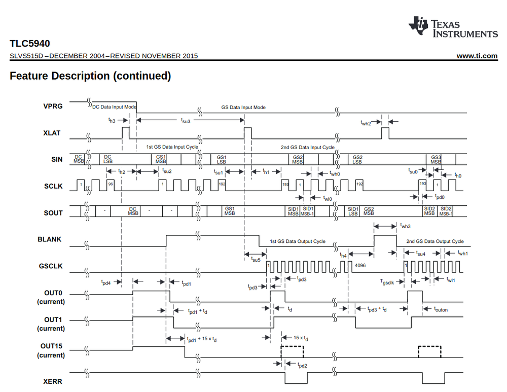
It's a little hard to make out, but paying attention to the BLANK and GSCLK signals, we see the IC requires 4096 pulses on GSCLK followed by a high pulse on BLANK. GSCLK is the PWM clock source for the IC, so no outputs will be enabled if it's absent. For some reason, BLANK needs a pulse every 4096 cycles to get the IC to continue functioning. We'll pay attention to the timing requirements later.

Hardware options

While we could of course use loops and counters to manually toggle the BLANK and GSCLK pins, on ESP32 there's a really nice peripheral called the RMT (Remote Control Receiver) which:

The RMT (Remote Control Transceiver) peripheral was designed to act as an infrared transceiver. However, due to the flexibility of its data format, RMT can be extended to a versatile and general-purpose transceiver, transmitting or receiving many other types of signals.

We don't care about receiving anything, but we can use the two transmit channels of the RMT to generate the pulse trains we need. The RMT is configured by specifying high or low pulses of varying duration. The key reason to use the RMT is it can be set up to repeat its configured pulse train without any intervention in code, freeing the MCU up for other business logic tasks.

Channel configuration

We'll configure channel 1 for the GSCLK waveform. The RMT only allows a few pulses to be provided, but we can use the carrier frequency generation block of the RMT to generate a high frequency PWM signal on the output while in an "on" pulse. All we need to do then is provide an "on" pulse with a duration of 4096 cycles to generate the correct number of GSCLK pulses.

The timing diagram from above shows that GSCLK must be disabled while the BLANK pin is high, so we'll specify a second "off" pulse to disable the carrier while we perform the BLANK pulse on channel 2.

Channel 2 of the RMT will be for the BLANK pulse, and behaves as the inverse of channel 1, however does not require the carrier to be enabled as we don't want a high frequency clock on the BLANK pin.

Synchronising the channels

The RMT can be told to synchronise both its channels. This is important for our use case to ensure the BLANK pulse lies in the idle period between GSCLK pulse trains.

Some code

I'm using the ESP HAL for its nice high level API, but at the end of the day all we're doing is writing register values, so the following solution should work in any software stack. Also, I'm using an ESP32-C3 but I believe the RMT is available in most/all Espressif ICs.

Here's the RMT configuration in full:

// Choose your own adventure
let gsclk_pin = io.pins.gpio1;
let blank_pin = io.pins.gpio2;

// GSCLK frequency defined here
let rmt = Rmt::new(peripherals.RMT, 2.MHz(), &clocks, None).unwrap();

// `GSCLK` config: when an "on" pulse is given,
// output a pulse train at half the configured RMT frequency
let gsclk_config = rmt::TxChannelConfig {
    // Divide input clock by 2 so specifying 4096 in
    // `PulseCode.length` gives us 4096 pulses.
    clk_divider: 2,
    // Idle low (pulses are active high)
    idle_output_level: false,
    // Don't output carrier when idle
    idle_output: false,
    // We're using the carrier modulation feature of the
    // RMT to generate the GSCLK PWM signal
    carrier_modulation: true,
    // 1 tick high
    carrier_high: 1,
    // 1 tick low = 50% carrier duty cycle
    carrier_low: 1,
    // Carrier pulse is active high
    carrier_level: true,
};

// `BLANK` is simpler - we just make an "on" pulse after
// 4096 `GSLK` pulses
let blank_config = rmt::TxChannelConfig {
    clk_divider: 2,
    ..rmt::TxChannelConfig::default()
};

// `GSCLK` pulses: 4096 cycles of carrier, followed by
// 64 cycles for `BLANK` pulse on channel 2
let gsclk_pulses = [
    PulseCode {
        // "on" pulse where carrier is output
        level1: true,
        length1: 4096,
        // "off" pulse for 64 ticks for BLANK pulse
        level2: false,
        length2: 64,
    },
    PulseCode::default(),
];

// Spacing around `BLANK` pulse to meet timing
// requirements in datasheet
let blank_spacing = 16;

// BLANK pulse
let blank_pulses = [
    PulseCode {
        // "off" pulse for 4096 cycles (plus breathing room)
        // while `GSCLK` is output
        level1: false,
        length1: 4096 + blank_spacing,
        // "on" pulse for `BLANK`
        level2: true,
        length2: 64 - blank_spacing - blank_spacing,
    },
    PulseCode {
        // "off" pulse for time spacing around end of `BLANK` pulse
        level1: false,
        length1: blank_spacing,
        // Noop; just here to complete the API
        level2: false,
        length2: 0,
    },
    PulseCode::default(),
];

// Enable CH0/CH1 sync (manual 33.3.4.5).
{
    let rmt = unsafe { &*esp_hal::peripherals::RMT::ptr() };

    rmt.tx_sim().write(|w| {
        w.tx_sim_ch0().set_bit();
        w.tx_sim_ch1().set_bit();
        w.tx_sim_en().set_bit()
    });
    rmt.ch_tx_conf0(0).modify(|_, w| w.conf_update().set_bit());
    rmt.ch_tx_conf0(1).modify(|_, w| w.conf_update().set_bit());
}

let channel0 = rmt.channel0.configure(gsclk_pin, gsclk_config).unwrap();
let channel1 = rmt.channel1.configure(blank_pin, blank_config).unwrap();

channel0
    .transmit_continuously(&gsclk_pulses)
    .expect("TX continuous");
channel1
    .transmit_continuously(&blank_pulses)
    .expect("TX continuous");

This code is a bit of a handful and difficult to understand, but the visualisations in the next section should hopefully clarify what the configuration is doing.

Before that though, I'll draw attention to a couple of things:

  1. There isn't yet a high level API to enable channel sync, so I'm dropping down into the PAC (Peripheral Access Crate) to manually set some bits.
  2. We call transmit_continuously to repeat the configured pulse train indefinitely.
  3. The blank_spacing variable adds some gaps around the BLANK pulse. I'll discuss this in Tighter timing below.

Behaviour

Here's what we see in PulseView, a logic analyser GUI:

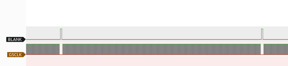
We can see a repeating pattern of high frequency PWM (the grey mess), interrupted by a BLANK pulse on the other line.

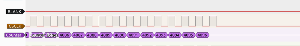
If we zoom in to the end of a cycle, just before the BLANK pulse, Pulseview shows us that 4096 pulses have been sent:

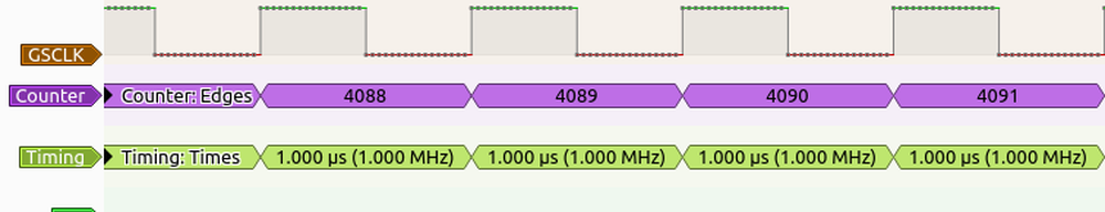
It also confirms the desired 1MHz frequency:

Now let's turn out attention to the BLANK pulse:

We can see it's nicely separated from the GSCLK pulse train, and is suitably long for the IC to register it.

Tighter timing

Let's take a closer look at the timing around the BLANK pulse:

The code in this post is extremely conservative, meaning we're leaving performance on the table, and potentially introducing undesirable flicker in any attached LEDs. We can probably do better, starting by figuring out what the datasheet specifies as "better". Looking at the timing diagram above, it makes reference to several excitingly named parameters like th4, twh3, etc. The values for these times are defined in the datasheet section "6.3 Recommended Operating Conditions". I'll copy the relevant ones for BLANK timing here:

Minimum time
th4Hold time GSCLK ↑ to BLANK10ns
twh3BLANK pulse duration10ns
tsu4Setup time BLANK ↓ to GSCLK10ns

A minimum of 10ns. Nice. Are we near these minimums?

Lol. Not even close. Here's the minimum times against what we configured:

Minimum timeOurs lmao
th4Hold time GSCLK ↑ to BLANK10ns16500ns
twh3BLANK pulse duration10ns32031ns
tsu4Setup time BLANK ↓ to GSCLK10ns16500ns

We're 3 orders of magnitude safe, so I think we can probably do better in our RMT configuration. The maximum frequency on GSCLK is 30MHz, although I don't think the RMT can reach even half that frequency (remember, the GSCLK pulse train is at half the RMT peripheral clock), but we could simply bump the RMT peripheral clock as an easy step in the right direction.

The better option would be to reduce blank_spacing in the example code from above, as well as fiddling with the BLANK pulse duration. This is RMT clock dependent however, so I'll leave it as an exercise to the reader.

A full example

Here's an example using Embassy which just fades all outputs up and down in a loop:

#![no_std]
#![no_main]

use embassy_executor::Spawner;
use embassy_time::{Duration, Timer};
use esp_backtrace as _;
use esp_hal::{
    clock::ClockControl,
    dma::{Dma, DmaPriority},
    dma_descriptors,
    gpio::{Io, Level, Output},
    peripherals::Peripherals,
    prelude::*,
    rmt::{self, PulseCode, Rmt, TxChannel, TxChannelCreator},
    spi::{master::dma::WithDmaSpi2, SpiMode},
    system::SystemControl,
    timer::timg::TimerGroup,
};

#[main]
async fn main(_spawner: Spawner) -> ! {
    esp_println::logger::init_logger_from_env();

    let peripherals = Peripherals::take();

    let system = SystemControl::new(peripherals.SYSTEM);
    let clocks = ClockControl::max(system.clock_control).freeze();
    let io = Io::new(peripherals.GPIO, peripherals.IO_MUX);

    let timg0 = TimerGroup::new_async(peripherals.TIMG0, &clocks);
    esp_hal_embassy::init(&clocks, timg0);

    // Parameter is length in bytes
    let (mut spi_tx_descriptors, mut spi_rx_descriptors) = dma_descriptors!(128);

    let mut spi = {
        let sclk = io.pins.gpio3;
        let mosi = io.pins.gpio4;

        let dma = Dma::new(peripherals.DMA);

        let dma_channel = dma.channel0;

        esp_hal::spi::master::Spi::new(peripherals.SPI2, 100.kHz(), SpiMode::Mode0, &clocks)
            .with_sck(sclk)
            .with_mosi(mosi)
            .with_dma(dma_channel.configure_for_async(
                false,
                &mut spi_tx_descriptors,
                &mut spi_rx_descriptors,
                DmaPriority::Priority0,
            ))
    };

    let mut xlat = Output::new(io.pins.gpio5, Level::Low);

    let gsclk_pin = io.pins.gpio1;
    let blank_pin = io.pins.gpio2;

    {
        // GSCLK frequency defined here
        let rmt = Rmt::new(peripherals.RMT, 2.MHz(), &clocks, None).unwrap();

        // `GSCLK` config: when an "on" pulse is given,
        // output a pulse train at half the configured RMT frequency
        let gsclk_config = rmt::TxChannelConfig {
            // Divide input clock by 2 so specifying 4096 in
            // `PulseCode.length` gives us 4096 pulses.
            clk_divider: 2,
            // Idle low (pulses are active high)
            idle_output_level: false,
            // Don't output carrier when idle
            idle_output: false,
            // We're using the carrier modulation feature of the
            // RMT to generate the GSCLK PWM signal
            carrier_modulation: true,
            // 1 tick high
            carrier_high: 1,
            // 1 tick low = 50% carrier duty cycle
            carrier_low: 1,
            // Carrier pulse is active high
            carrier_level: true,
        };

        // `BLANK` is simpler - we just make an "on" pulse after
        // 4096 `GSLK` pulses
        let blank_config = rmt::TxChannelConfig {
            clk_divider: 2,
            ..rmt::TxChannelConfig::default()
        };

        // `GSCLK` pulses: 4096 cycles of carrier, followed by
        // 64 cycles for `BLANK` pulse on channel 2
        let gsclk_pulses = [
            PulseCode {
                // "on" pulse where carrier is output
                level1: true,
                length1: 4096,
                // "off" pulse for 64 ticks for BLANK pulse
                level2: false,
                length2: 64,
            },
            PulseCode::default(),
        ];

        // Spacing around `BLANK` pulse to meet timing
        // requirements in datasheet
        let blank_spacing = 16;

        // BLANK pulse
        let blank_pulses = [
            PulseCode {
                // "off" pulse for 4096 cycles (plus breathing room)
                // while `GSCLK` is output
                level1: false,
                length1: 4096 + blank_spacing,
                // "on" pulse for `BLANK`
                level2: true,
                length2: 64 - blank_spacing - blank_spacing,
            },
            PulseCode {
                // "off" pulse for time spacing around end of `BLANK` pulse
                level1: false,
                length1: blank_spacing,
                // Noop; just here to complete the API
                level2: false,
                length2: 0,
            },
            PulseCode::default(),
        ];

        // Enable CH0/CH1 sync (manual 33.3.4.5).
        {
            let rmt = unsafe { &*esp_hal::peripherals::RMT::ptr() };

            rmt.tx_sim().write(|w| {
                w.tx_sim_ch0().set_bit();
                w.tx_sim_ch1().set_bit();
                w.tx_sim_en().set_bit()
            });
            rmt.ch_tx_conf0(0).modify(|_, w| w.conf_update().set_bit());
            rmt.ch_tx_conf0(1).modify(|_, w| w.conf_update().set_bit());
        }

        let channel0 = rmt.channel0.configure(gsclk_pin, gsclk_config).unwrap();
        let channel1 = rmt.channel1.configure(blank_pin, blank_config).unwrap();

        channel0
            .transmit_continuously(&gsclk_pulses)
            .expect("TX continuous");
        channel1
            .transmit_continuously(&blank_pulses)
            .expect("TX continuous");
    }

    let mut send_buffer = [0u8; 24];

    let mut value = 0i16;
    let mut inc = 100i16;

    loop {
        let frame = [value as u16; 16];

        // Pack 16 bit pixel values into frame buffer for 12 bit outputs
        for (idx, chunk) in frame.chunks(2).enumerate() {
            // Byte index start location
            let idx = idx * 3;

            if let [a, b] = chunk {
                let low: u16 = (a & 0x0ff0) >> 4;
                let mid: u16 = ((a & 0x000f) << 4) | ((b & 0x0f00) >> 8);
                let high: u16 = b & 0x00ff;

                send_buffer[idx] = low as u8;
                send_buffer[idx + 1] = mid as u8;
                send_buffer[idx + 2] = high as u8;
            }
        }

        embedded_hal_async::spi::SpiBus::write(&mut spi, &send_buffer)
            .await
            .unwrap();

        // Pulse XLAT to update outputs
        xlat.set_high();
        xlat.set_low();

        value += inc;

        if value > 4095 || value <= 0 {
            value = value.max(0).min(4095);

            inc *= -1;
        }

        Timer::after(Duration::from_millis(10)).await;
    }
}